Calculating Line Impedance
The line impedance subroutine was been extracted from BPA’s Electromagnetic Transients Program (EMTP) and modified for computing a balanced pi-equivalent line section. You can find a clone of BPA’s EMTP The line impedance calculation feature is invoked from the branch data dialog. See the screenshot, diagram, and table below. It calculates the pi-equivalent quantities from the conductor type, conductor bundling, and tower geometry. The following applies to all calculations:
There is continuous transposition of phases.
Resistivity is calculated at 25 degrees Celsius.
Earth resistivity is constant at 100 ohm-meters.
The Line Impedance dialog box consists of three panels for data.
Conductor Values. This is the scrollable list of conductor data, which is usually imported from a line constants data file.
Edit Conductor. This is the only means to edit data.
Calculate Impedance. This output panel displays the pi-equivalent data.

Fig. 155 Line Impedance Calculation Dialog Box
Description of Conductor Data Fields
Each physical conductor is characterized by a number of items that you need to specify. The following list describes these items:
UNITS Allows you to specify either metric or English units.
BASEKV The base value for the voltage in kV.
BASE MVA The base value for the power in MVA. (Default is 100.0.)
NAME Common conductor bird names are hard-coded. In Edit mode, selecting a name
from the button menu automatically transfers O.D.``(outside diameter), ``SKIN, and
RESIS data to the pertinent field. If any of these fields are modified, the
conductor name becomes “other.”
IPHASE The phase number (an integer) to which this conductor belongs. Specify as zero for a ground wire (ground is phase number zero by definition). If more than one conductor is specified with the same phase number, this means that those conductors are to be bundled (electrically connected in parallel). Use numbers 1, 2, etc., without any missing (unused) entries, when you number the phases. In general, 1, 2, 3 pertain to circuit1, phases a, b, c, respectively; 4, 5, 6 pertain to circuit2, phases A, B, C, respectively.
SKIN A field that is specified with the ratio T/D, where: T is the thickness of the tubular conductor. D is the outside diameter of the tubular conductor. For a solid conductor, use 0.5.
RESIS The dc resistance of the conductor in ohms/kilometer if metric or ohms/mile if English.
DIAM Outside diameter of the a tubular conductor in centimeters if metric or inches if English.
HORIZ Horizontal separation of the center of the conductor from some reference line in meters if metric or feet if English. The location of the horizontal reference line is arbitrary. Distances to the right of the center line are positive, while those to the left are negative.
VTOWER Vertical height of the conductor above the ground at the tower in meters if metric or feet if English.
VMID Vertical height of the conductor above the ground at mid-span (midway between two towers) in meters if metric or feet if English.
Note
The average height of the line is calculated by the following equation if both the VTOWER and VMID fields are specified non-zero.
If either data field is left blank, the blank field defaults to the other field. In effect, the user specifies the average height.
SEPAR ALPHA Leave this blank unless the automatic bundling option is desired.
FREQ The frequency, \(f\), of the line impedance calculation in units of Hertz.
DIST The length of the transmission line under consideration in kilometers if metric or miles if English.
NBUND Leave this blank unless the following automatic bundling option is desired.
AUTOMATIC BUNDLING OPTION
Rather than specifying each conductor of a bundle individually, there is an automatic bundling option that allows a single conductor data to suffice for specifying the entire bundle. This can be used for a “regular” bundle, where by definition all component conductors are identical, and such conductors are also assumed to be uniformly spaced around the circumference of a circle.
Automatic bundling uses the data fields SEPAR, ALPHA, and NBUND, which are otherwise left blank. The “conductor” data then becomes “bundle” data according to the following specifications:
SEPAR The separation between adjacent conductors in the bundle in centimeters if metric or inches if English.
ALPHA The angular position of the first conductor (or any conductor) of the bundle in units of degrees. Positive angles are measured counter-clockwise as shown in Figure C-1.
NBUND The number of conductors that make up the bundle. Or, if you specify by name, separ, and alpha, nbund will be supplied by the program. (For names, see table above under Bundle at the 500 kV lines.)
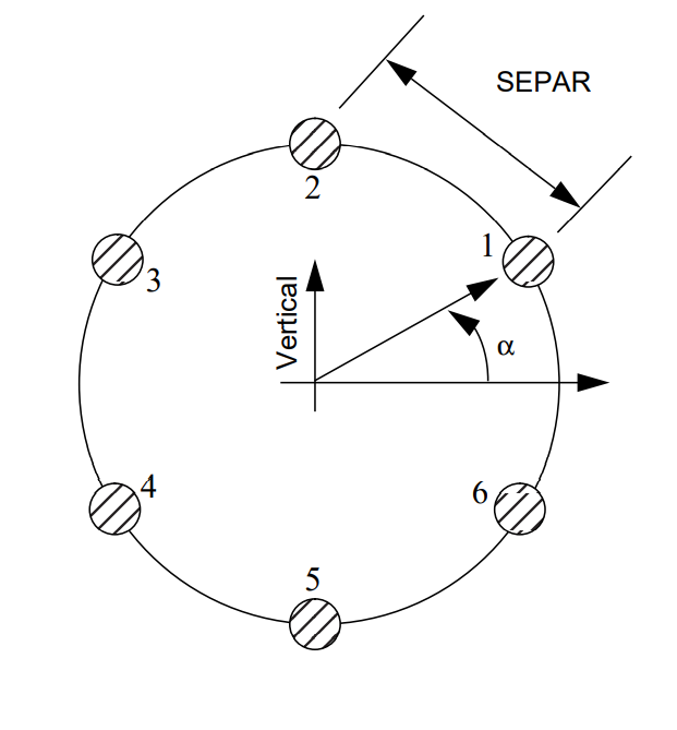
Fig. 156 A Six Bundle Conductor
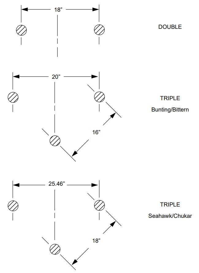
Fig. 157 BPA Conductor Bundles
Output Values
Considerable data is required to compute the pi-equivalent for a single segment. The line impedance dialog is most effective when importing files containing line impedance data.
A typical file contains ASCII data in free-field format. The file types are .lcd for “line conductor
data.” The following is an example.
/GET_DATA, TYPE = LINE_IMPEDANCE_CALCULATION
 UNITS = < ENGLISH | METRIC >, DISTANCE = < miles | km >
 BASEKV = <basekv>, BASEMVA = <basemva>, FREQUENCY = <freq>
 CONDUCTOR = 1 .3636 .05215 1.602 -20.75 50. 50. 0.0 0.0 0
 CONDUCTOR = 1 .3636 .05215 1.602 -19.25 50. 50. 0.0 0.0 0
 CONDUCTOR = 2 .3636 .05215 1.602 -0.75 77.5 77.5 0.0 0.0 0
 CONDUCTOR = 2 .3636 .05215 1.602 0.75 77.5 77.5 0.0 0.0 0
 CONDUCTOR = 3 .3636 .05215 1.602 19.25 50. 50. 0.0 0.0 0
 CONDUCTOR = 3 .3636 .05215 1.602 20.75 50. 50. 0.0 0.0 0
 CONDUCTOR = 0 .5 2.61 0.386 -12.9 98.5 98.5 0.0 0.0 0
 CONDUCTOR = 0 .5 2.61 0.386 12.9 98.5 98.5 0.0 0.0 0
The usual scenario involves the following steps.
Import a relevant
.lcdfile using the Use Saved button.Edit the file to reflect the geometric and physical attributes of the line under consideration.
Calculate the pi-equivalent data. Steps 2 and 3 may be iterated as long as necessary to eliminate errors.
Export the modified
.lcdfile using the Save Values button.If the results are acceptable, automatically transfer the positive sequence values back to the line dialog by pressing the OK button. (The zero sequence values are for inspection only.)
If the results are not acceptable, press the Close button. No values are transmitted back to the line dialog by a Close action.
Calculating the Impedance
After you have supplied all the necessary values for the line impedance calculations, you can click on the Calculate Impedance button in the Line Impedance Calculation dialog box. The program fills in six numbers in per unit values having the following meanings:
R/Z1 transfer Real part of the positive sequence transfer impedance per unit.
X/Z1 transfer Imaginary part of the positive sequence transfer impedance per unit.
R/Z1 shunt Half value of the real part of the positive sequence shunt admittance per unit.
X/Z1 shunt Half value of the imaginary part of the positive sequence shunt admittance per unit.
R/Z0 transfer Real part of the zero sequence transfer impedance per unit.
X/Z0 transfer Imaginary part of the zero sequence transfer impedance per unit.