Overview
You can interact with IPF using the Command Line Tools (bpf, ipfbat, ipfcut,
etc.), the X Window Graphical Interface (gui) or the CFLOW C API (libcflow). Many of the
functions and features of the command line tools are available through specially designed GUI
features. The GUI simplifies creating network data, running the base case solutions, and
graphically visualizing the network diagrams.
IPF Interaction Model
The conceptual model of IPF is quite simple. You load power system network data into IPF; the IPF solution “engine” performs the calculations for the solution, and then outputs this solution data.
IPF offers different approaches to accomplish power system solutions. Their style of interaction and processing are quite different.
The batch power flow (e.g. bpf or ipfnet) approach. This is an Input-Process-Output approach. You write a command file containing all of the “orders” that you want filled, and the program performs the actions it determines are necessary to produce the ordered results.
The Graphical User Interface (GUI) approach. This is command oriented - you click a button or enter a command, and it is executed immediately by the backend power flow engine (
ipfsrv).The CFLOW approach (the C API called
libcflow). This is a programming based approach where you write C code to interact with IPF.
Two Domain Specific Languages (DSLs) called Powerflow Command Language (PCL) and Power Flow
Control (PFC) allow users to define the “scenarios” or “orders”. PCL is directly available
through a Command Dialog window in the X Window GUI and can be used with the ipfbat
program. PFC is used with the bpf program. See Power Flow Control (PFC) for details of
the PFC syntax and Powerflow Command Language (PCL) for details of the PCL sytanx.
Note
The PFC syntax was developed first and later Bonneville Power Administration (BPA) added the PCL syntax. They referred to PCL as the “new style”, and the PFC as the “old style”. These two sets of commands are not completely compatible even though the “new style” command set and syntax is closely modeled on the “old style.”
The bpf Batch Approach
When you use bpf, you must first create a Powerflow Command Language (PCL) file with
the appropriate commands to accomplish the solution task at hand. At runtime these commands
are accepted by ``bpf``and executed according to a logical processing order determined by
the program. Hence you need not be concerned with the ordering of commands in your PFC file.
Input commands will be processed first, and a solution done automatically before any output is produced.
Finally, a new base file will be created, if you have requested one. See
PFC Examples for examples of PFC files.
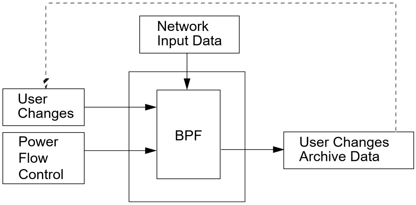
Fig. 2 BPF Information Flow Model
The ipfbat Batch Approach
ipfbat allows you to interact with the solution “engine” (ipfsrv) without the
GUI. You first create a PCL file with the appropriate commands, in the right order, to
accomplish the solution task at hand. At runtime these commands are interpreted by
ipfbat. The PCL file commands are processed sequentially. Additional PCL command
files may be specified by name, so that a “chain” of PCL files may be processed in one
run.
The GUI Approach
When you use the GUI approach, you use an X Window graphical interface with dialog boxes,
menus, windows, etc. This makes data input, output, and manipulation easy. In addition
to allowing basic case solution tasks to be accomplished, certain specialized tasks such
as line impedance calculations are available. See Calculating Line Impedance for
details. However, for more involved tasks, you’ll need to use the bpf approach. For
information about how to work with the GUI dialog boxes, menus, windows, etc., see
X Window Graphical Interface (gui). That section also has a tutorial to show you how to
solve straightforward power system cases.
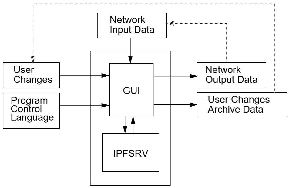
Fig. 3 PCL Information Flow Model
The core powerflow engine (ipfsrv) can be ran on separate machine from the graphical
user interface. These two (gui and ipfsrv) processes are joined by interprocess
communication (IPC) routines that shuttle data and instruction messages back and forth
between the GUI and powerflow program using sockets. ipfsrv serves primarily as a
solution and data engine that sends and receives data when requested by the user through
the GUI.
The CFLOW Approach
Many times users need to do a large number of similar runs or they need to process data
from another system or set of files before running studies. CFLOW is a C library API
(libcflow) for IPF. To use CFLOW, you write a C program, including the header file
cflowlib.h, which defines all the structures, unions, and functions which allow
access to the powerflow input and solution. To retrieve solution values, you call
various CFLOW functions. The API interacts with ipfsrv interally. This allows you
to do things like ask for a new solution, change the model, etc. See
CFLOW C API (libcflow) for details on the API and examples.
Executables
IPF consists of many executable programs. Several of the most common executables are briefly described below.
bpfCommand line program that performs power flow.
bpfis the batch form of the powerflow program and unlikeipfsrvit doesn’t use socket communication to interact with the powerflow engine. Rather it uses direct code library linking. It allows one or more scenarios to be defined in input files and run all at once via a call tobpffrom a command line terminal. It executes using the commands from a Power Flow Control (PFC) file. Example usage:bpf bench.pfc.The PFC commands (i.e. the content of the .pfc file) used withbpfallow for complete power flow runs including defining the network model and commands to perform various operations. The Record Formats section describes the network model records available and the Power Flow Control (PFC) section describes the PFC syntax and commands available. More documentation about this program is in bpf section.
guiLaunches the Graphical User Interface program built with `Motif X Window`_ that works in conjunction with the power flow server,
ipfsrv. When the editing and displaying of buses and branches is being handled by theguiprocess, the work of calculating solution voltages for a given power system network is done byipfsrv, which is just thebpfprogram in a different guise. More documentation about this program is in X Window Graphical Interface (gui) section.
ipfsrvThe power flow service daemon which runs as the backend component of the
gui. It executes Powerflow Command Language (PCL) commands through scripts dispatched from thegui. See ipfsrv for more details.
ipfbatCommand line program that is the batch version of
ipfsrv. It accepts a Powerflow Command Language (.pcl) file. Plotting can be done with a control file; however, for most plotsipfplotis easier to use. Example of use:ipfbat bench.pcl. The PCL commands used withipfsrvandipfbatare described in Powerflow Command Language (PCL).
ipfcutCommand line program that cuts out a subsystem from a solved base case file (.bse). Flows at the cut branches are converted into equivalent generation or load on specially formatted
+Acontinuation bus records (read more about Continuation Bus Data (+)). An ensuing power flow run should solve with internal branch flows and bus voltages which are identical to those quantities in the original base case. More documentation about this program is in ipfcut section. Several methods are available to define the cut system: bus names, zones, base kVs, and individual branches. A pi-back feature replaces selected buses with a passive-node sequence (lines consisting of sections) with the original loads pi-backed in proportion to the line admittances.
ipfplotCommand line plotting program to produce printed maps in batch. The program accepts a coordinate file (.cor) and a base case file (.bse) on the command line, as well as an optional second base case file. When the second base case file is specified, a difference plot is produced. You can also use
ipfplotto produce bubble diagrams. The same coordinate files are used for bothguiandipfplot, but not all capabilities are available ingui. Documentation is in Network Diagrams. More documentation about this program is in ipfplot section.
tspCommand line program that performs transient stability studies. Users specify power system network distrubances (line faults, generator trips), and the program simulates the affects on power system dynamics including key data points like generator rotor angle. This tool can be used to evaluate short term (on order of seconds to minutes) affects of these disturbances. Example of use:
tsp bench.fil. More documentation about this program is in Transient Stability Program (tsp) section.
ipfnetThe command line batch version of the “save netdata file” command built into the
gui/ipfsrv. This program generates a WSCC-formatted network data file in any of the following dialects: BPA, WSCC, or PTI. “Dialects” means that the file is still WSCC, but the data is generated with special processing or restrictions and is destined for use with other programs. In the case of the PTI dialect, that data is preprocessed by the PTI-proprietary conversion program WSCFOR. Detailed documentation is in ipfnet.
ipf_reportsThe command line report tool to create output reports and summaries from solved base cases (.bse). Enter
ipf_reportsfrom the command line and follow the prompts.
ips2ipfThe program that converts a network data file from WSCC’s Interactive Powerflow System (IPS) format to IPF format. Duplicate buses are renamed; Load Tap Changer (LTC) steps are converted to taps, shunt susceptance on slack and
BQbuses are transferred to+Arecords; sectionalized lines containing a section 0 are renumbered 1, 2, … ;BX,X, and remote controlled bus data are converted to IPF format, etc. Documentation is in IPS IPF Differences.
Network Data
A core component to any power system analysis problem is the power system network (the interconnected lines, generators, loads, transformers, nodes/buses, breakers, and other components). In IPF, this is referred to as Network Data. Network Data defines the structure (connectivity) and properties (base voltage, real power injections, real and reactive power loads, transformer tap settings, etc.) of the power system network. This data is defined in files that contain bus (nodes) and branch (lines, transformers, etc.) records. Most of the input files are ASCII text files. But one important file, the base case file (.bse), is in binary format. You can, of course, edit ASCII text files with any text editor. This is often done, but your data integrity is safer if you do all the editing you can in the GUI. The base case binary file cannot be edited with an ordinary text editor, but can in effect be edited via the GUI when you have a base case file loaded.
There are multiple methods for specifying the Network Data. The following is a list of the various methods with descriptions.
.pfc
This input file contains job control information for the
bpfprogram. This file may contain Network Data explicitly (listing out Record Formats right in the file), but more often includes a property calledNETWORK_DATAthat specifies a file containing the Record Formats in ASCII format. Alternatively, users can specify a property calledOLD_BASEthat specifies a base case (.bse) file, or other job control data to be described. Keeping the Network Data out of the.pfcfile allows more clear separation between the commands of the batch study and the network model.You can edit this file using any ASCII text editor to add, modify, and delete commands and data records. See PFC Examples for examples.
NETWORK_DATA
This ASCII text input file consists of area, bus, and branch records. It must not contain modification records.
This file can be maintained by using an ASCII text editor. Or you can edit the records you want in the GUI through the various dialog boxes and then save a new
NETWORK_DATAfile. In the file, data records may be in random order, but actual processing is done in the following order:
Area interchange records.
Each area record identifies a composition of zones whose member (associated) buses define specific aggregate quantities that may be controlled to specified export values.
A(Area interchange records)
I(Area intertie records)
Bus data record group containing at least two records.
Each bus data record identifies one bus in the network. Buses are uniquely identified by their bus name and base kV.
B(Bus records)
+(Continuation bus records)
X(Switched Reactance records)
Q(PQ Curve data records)
Branch data record group containing at least one record.
L(AC or DC Transmission line records)
E(Equivalent Branch records)
T(Transformer records)
R(Regulators (Automatic or LTC transformer) records)Branch data entered in any of the ASCII files is single-entry or one-way only. This means, for example, that a branch connecting buses A and B has a user-submitted entry (A,B) or (B,A) but not both. The program transposes the record internally as required during execution. Normally which way the branch is entered does not matter, but it does affect the default end metered on a tie line, and the physical position of line sections. See Record Formats, for a discussion of this feature.
Branches are uniquely identified by three fields:
Their terminal bus names and base kVs.
Their circuit or parallel ID code.
Their section code.
BRANCH_DATA
This ASCII text input file contains the branch data of all branches coded with in-service date and out-of-service date. This file is searched for branches in service on the date requested.
bpfselects the appropriate branches.
NEW_BASE
This program-generated, binary output file contains complete base network data and steady-state operating values for the case being processed. This file is identical in format to the
OLD_BASEfile.NEW_BASEsimply designates the file when it is produced as the output from a recently concluded case study. See The BASE (.bse) File section for more details on this file.
OLD_BASE
This program-generated, binary input file contains complete base network data and steady-state operating values. This file is identical in format to the
NEW_BASEfile.OLD_BASEsimply designates the file when it functions as an already existing input file. See The BASE (.bse) File section for more details on this file.
CHANGE
This ASCII text input file contains changes (new and modification records) to the data input from any combination of
NETWORK_DATA,BRANCH_DATA, andOLD_BASEfiles making up the case to be studied. These change records change the input data for the base case.
Printout File .pfo
This is an ASCII text output file that contains bus, branch, and solution data from a completed case study and is intended for ordinary, paper hardcopy output.
Microfiche file .pff
This is a special format output file that contains bus, branch, and solution data from a completed case study and is intended for microfiche format.
File |
Format |
Input/Output (I/O) |
Created by |
Editing |
Information Contained |
|---|---|---|---|---|---|
|
ASCII |
|
User |
Yes |
Bus, Branch, Commands, File Names |
|
ASCII |
|
User |
Yes |
Commands, File Names |
NETWORK_DATA |
ASCII |
|
User gui ipfnet |
Yes |
Bus, Branch |
BRANCH_DATA |
ASCII |
Input Only |
User |
Yes |
Branch |
OLD_BASE |
Binary |
Input Only |
IPF |
No |
Bus, Branch, Solution Values |
CHANGES |
ASCII |
Input or Output |
User |
Yes |
Bus, Branch, Modifications |
NEW_BASE |
Binary |
Output Only |
IPF |
No |
Bus, Branch, Solution Values |
Printout file (<name>.pfo) |
ASCII |
Output Only |
|
No |
Input Data and Solution Reports, User Analysis |
Microfiche file (<name>.pff) |
ASCII |
Output Only |
|
No |
Input Data and Solution Reports, User Analysis |
Debug file (<name>.pfd) |
ASCII |
Output Only |
|
No |
Solution arrays and iteration processing |
Printout file (<logon>.pfo) |
ASCII |
Output Only |
|
No |
Messages, Iteration Summary |
Debug file (<logon>.pfd) |
ASCII |
Output Only |
|
No |
Solution arrays and iteration processing |
The BASE (.bse) File
This file, designated OLD_BASE if you are loading it, or NEW_BASE if you are saving it, is binary in format and contains the following data:
The case identification, project ID, and two header records.
The date the case was generated.
The program version used to generate the file (so future program versions can read the file if file structures change).
Up to 100 comment records.